There is an active community of radio amateurs dedicated to hacking the Quansheng UV-K5 and variants. I count myself as one of them. In the linked article I show how to modify the hardware and […]
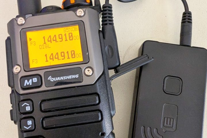
Highly mobile packet radio
There is an active community of radio amateurs dedicated to hacking the Quansheng UV-K5 and variants. I count myself as one of them. In the linked article I show how to modify the hardware and […]
The Kenwood TK-x90 series of radios are discontinued land-mobile radios used extensively in public safety (police/fire) in the US and which are currently available used for under $100. The VHF models can be converted to […]
The Motorola Radius SM-series radios are discontinued land-mobile radios (FCC Part 90) that are available used for under $50. The VHF models can be converted to work on the 2m band, making them an inexpensive […]
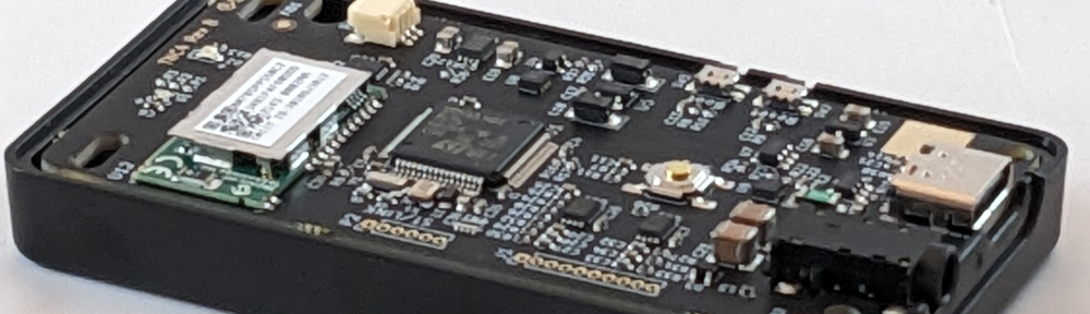
The test fixture created for programming and testing the TNC3 has been a great time-saver. Pogo pins on the test fixture mate with test points on the bottom of the TNC3 PCB. These are then […]
The NucleoTNC is a breadboard implementation of our commercial product, the Mobilinkd TNC3, designed to encourage experimentation and learning in amateur radio, electronics, digital signal processing and software engineering. The TNC can be built with […]
We recently posted a description of the demodulation technique used in the Mobilinkd TNC3 on our GitHub page: https://github.com/mobilinkd/afsk-demodulator/blob/master/afsk-demodulator.ipynb The post includes a complete demodulator written in Python. Note that GitHub does not render the […]
This is a follow up to A Brief Review of the KT-8900D Testing Turn-around Time One of the key metrics when evaluating a radio for packet use is turn-around time. This is the time it […]
Over the years we have received a few questions about inexpensive mobile rigs for use with our TNCs. Mostly what people are after are the cheap Chinese radios that can be had for around $100. […]
Create a Mobilinkd TNC on a breadboard for just a few dollars. The Mobilinkd TNC1 started its life, as with many things these days, as an Arduino project. It quickly took on a life of […]
This page provides instructions on how to modify the Mobilinkd TNC1 to allow it to track the Bluetooth connection state and to configure the TNC to drop packets when Bluetooth is disconnected. This is necessary […]