
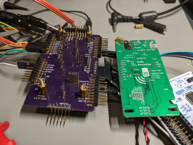
The test fixture created for programming and testing the TNC3 has been a great time-saver. Pogo pins on the test fixture mate with test points on the bottom of the TNC3 PCB. These are then brought out to header pins that can be attached to an oscilloscope, logic analyzer, frequency counter, or any other manner of test and development equipment.
However, all is not perfect.
I was reminded today that a test fixture, when used, becomes part of the overall circuit. And for sensitive analog circuits, this can cause problems.
Today I spent a few hours re-discovering the impact the test fixture has on the TNC3 audio output circuitry.
The TNC3 has a fairly wide audio output range, about 3 orders of magnitude or about 60dB. The low range, below about 100mV peak to peak, uses an attenuator (basically a voltage divider).
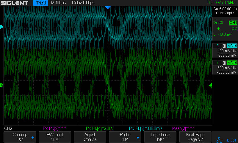
When the audio output attenuator is disabled, which is required for 9600 baud modulation, serious distortion was occurring in the audio output. This only occurred when on the test fixture.
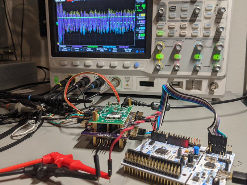
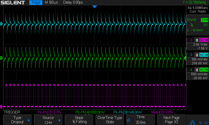
The clue that led to the to the source of the problem was capturing the noise alone, without a modulating signal. Note frequency counter on the oscilloscope (upper right) in the above image.
32 768 Hz is the frequency of the low speed oscillator on the TNC3.
The test points for the audio attenuator and the clock are next to each other. Their signals run parallel across the test fixture.
This couples digital noise at a very sensitive point in the analog circuitry.
When the attenuator is enabled, this noise is connected directly to ground so it doesn’t affect the audio. When disabled, the signal conducts straight into the audio path.
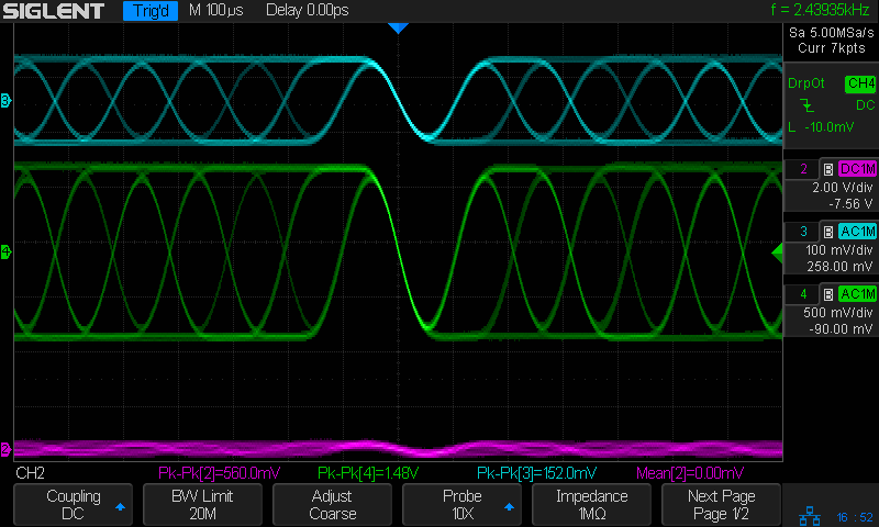
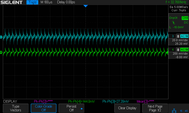
Disabling the clock output pin in the TNC3 firmware eliminates the noise when on the test fixture; we get a clean output signal.
And, in its place, we now see a faint hint of the audio signal being coupled to the (now unused) clock signal.
Lesson learned. One must understand the impact a test fixture will have on a DUT. And one must pay just as much attention to proper design principles when laying out a test fixture as one does when designing the device itself.