This page provides instructions on how to modify the Mobilinkd TNC1 to allow it to track the Bluetooth connection state and to configure the TNC to drop packets when Bluetooth is disconnected. This is necessary when using the TNC as a digipeater and iGate.
Please note: all TNCs that we currently sell include this feature. This page exists to help those that purchased their TNC before May 2014.
The Challenge
The Mobilinkd TNC from the factory queues packets indefinitely. That’s great when you walk away from the TNC with your smartphone in your pocket, and then come back a few minutes later. All the packets that were received by the radio and decoded by the TNC get queued in the Bluetooth module and then downloaded to your phone when you return. The only downside is that the packet times are a bit off.
Georg Lukas, DO1GL, the author of APRSdroid, mentioned that, in order to use the TNC as a digipeater, it is important that old packets are discarded. Otherwise it is possible that old packets are digipeated and iGated. This is bad behavior on APRS and affects everyone in range of the radio and possibly the world if acting as an iGate.
It has certainly happened to me while performing routine station maintenance on WX9O-4. I forgot to turn off the TNC while doing an hour of maintenance. When I brought up the APRS system, to my chagrin, a bunch of outdated packets were digipeated and iGated.
How do we make this work? This wasn’t a consideration when the TNC was designed.
The Solution
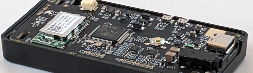
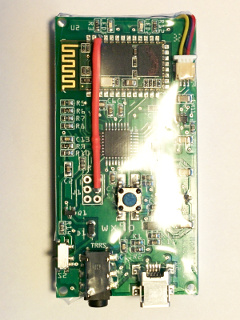
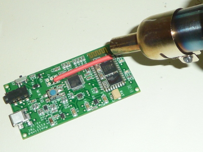
It turns out the Bluetooth module toggles one of its pins as the Bluetooth connection is established and dropped. But this pin is not connected to the TNC’s MCU (microcontroller). To make this work, we are going to need to break out the soldering iron!
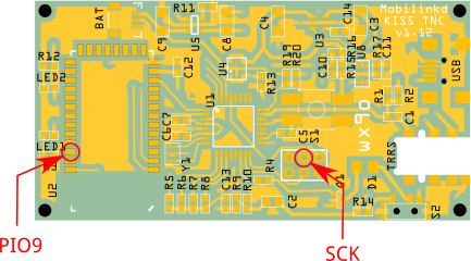
The BT module uses PIO9 to indicate connection status. It normally takes the pin high when connected and low when disconnected.
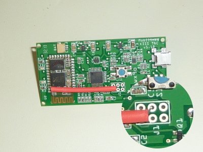
The TNC has an exposed ISP (in-system programming) pad that makes it possible to connect to three otherwise unused I/O pins on the MCU (MOSI, MISO and SCK, or PB3, PB4 and PB5). We just need to connect the PIO9 pin from the BT module to one of the pads.
After a bit of work on the TNC firmware and the Bluetooth module configuration, I found that it is possible to configure the pin on the MCU to read high when not connected and to configure the BT module to hold its pin high when the BT link is disconnected and set it low when connected. In this way, the only way the pin on the MCU goes low is when both connected to the BT module and the BT link is established. That allows the TNC to easily detect that it has been modified.
The Upgrade!
To make this work,a few things need to happen:
- A 4.7kΩ resistor needs to be soldered be soldered between the PIO9 pin on the Bluetooth module and the SCK pad on the ISP connector.
- The TNC firmware needs to be updated to a version that supports connection tracking.
- The Connection Tracking option in the firmware needs to be enabled.
Requirements
You will need a Mobilinkd TNC of course.
Parts
- 4.7kΩ resistor (1/8 watt)
- 2.5mm (.098″) shrink tubing cut to 37mm
- TNC shrink wrap
Tools
- X-acto knife
- Soldering iron with temperature control and a very fine tip
- Hot air gun (or a hot-air rework station)
- Solder braid
- Fine solder (.5mm/.020″) or solder paste
- Helping hands soldering stand
- Diagonal cutter
- Needle-nose pliers
- Electrical Tape
- ESD mat and wrist strap
Please do not attempt this modification if you do not have a good, temperature-controlled soldering iron.
Instructions
Be very careful of ESD (electro-static discharge). The TNC can be damaged if proper care is not taken. Perform the work on and ESD mat and use and grounded wrist strap.
Firmware
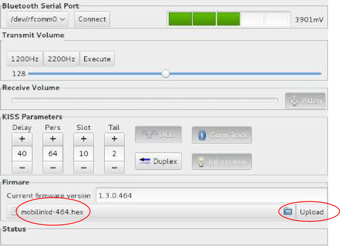
Start by upgrading the firmware to build 464 or later. (A more detailed post on upgrading the TNC firmware will follow.)
Disassembly
Start by removing the plastic wrap from the TNC. Be very careful not to cut yourself or the battery.
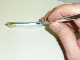
Use a sharp X-acto knife. Start with the hole by the slide switch. Work the blade toward the near end first. Then work the blade slowly and carefully towards the far end. A sharp blade should cut through the plastic fairly easily. Angle the blade towards the board and away from the battery.
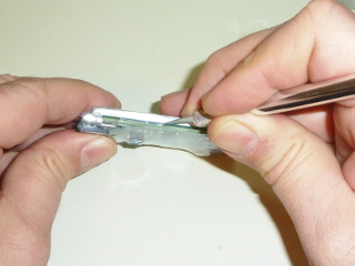
Peel the plastic away from the TNC and discard it.
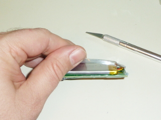
Unplug the battery from the TNC. Pull on the plug or pull on the wires near the plug. Do not pull on the battery. Put the battery aside.
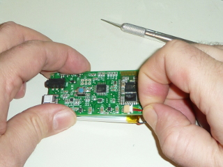
Modification
You will be soldering a 4.7kΩ resistor from PIO9 on the Bluetooth module to the SCK pad on the ISP pad. The resistor must be sheathed in shrink tubing to insulate it from the circuit board. Both ends of the resistor will be soldered from the top of the board.
Install a fine tip on your soldering iron and set the temperature to 315°C (600°F).
The amount of solder on the pads connecting the Bluetooth module varies. You may wish to remove some solder from the PIO9 pad before soldering the resistor to the pad. Use the solder braid to remove any excess solder on the pad.
Put a 2mm bend at one end of the resistor to form an “L”. Use the helping hands to hold the resistor on the PIO9 pad. This is the third pad from the end by the antenna, near the outer edge of the TNC circuit board. (Refer to the diagram above if unclear which pad to use.)
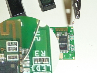
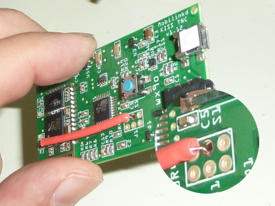
Solder the resistor to the pad.
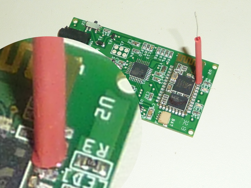
Slide the shrink tubing over the resistor.
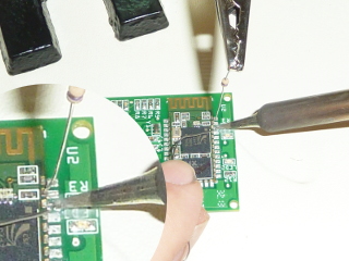
Bend the resistor over the circuit board and slide the free resistor lead through the SCK hole.
Solder the resistor to the hole from the top. Do not solder the resistor from the bottom of the circuit board. And do not use so much solder that it flows through to the other side of the through-hole. Doing either may later damage the battery.
Cut the lead flush to the bottom of the circuit board. It is important that the lead does not protrude through the hole.
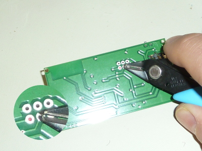
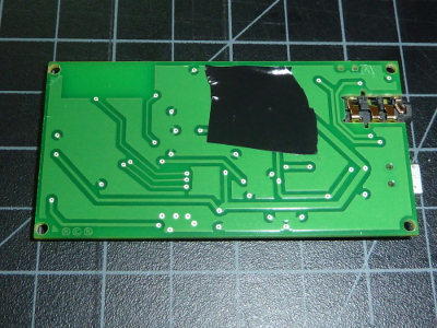
Cover the bottom of the pad with electrical tape to help protect the battery when reassembled. Press down firmly.
If the resistor lead pokes through the tape, the resistor lead is too long. Do not reassemble the unit in this condition. Remove the tape and cut the resistor lead flush and try again.
Set your heat gun to 155°C (310°F). Shrink the tubing.
Testing
Attach the battery. Wait at least 5 seconds then power on the device.
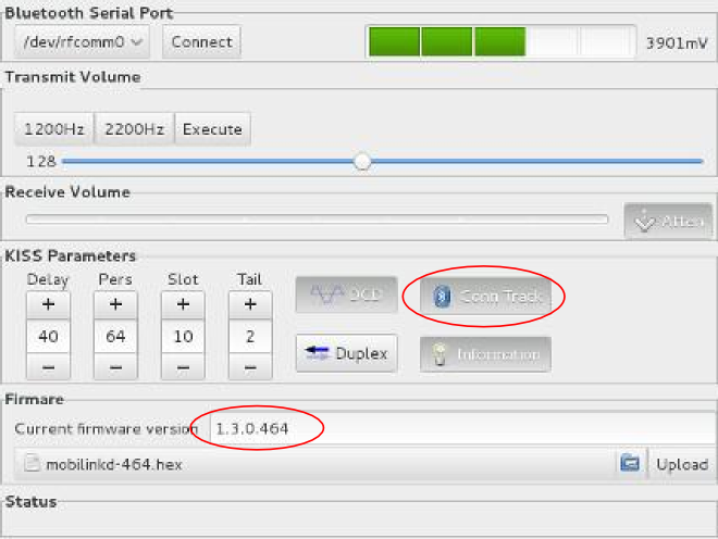
Start the Mobilinkd Configuration program and connect to the TNC. You should see the “Conn Track” button active. If it is not, verify that you have the latest version of the firmware installed and the lastest version of the configuration utility. (The Android verions 0.8.3 is known to work.)
Enable “Conn Track” on the TNC and then exit the configuration program. You should now find that the TNC receives packets only when the Bluetooth link is established.
Reassemble
The best option for re-assembly is to print or purchase a case!
The Mobilinkd TNC1 case is now a Thing on Thingiverse! If you have access to a 3D printer, you can print your very own. If not, we sell freshly printed cases in your choice of Black or White in the store: http://store.mobilinkd.com/collections/kits